How to test ICM and coil?
 12-29-2009, 06:04 PM
#1
Junior Member
Thread Starter
Join Date: Apr 2005
Location: United States of America
Posts: 216
Likes: 0
Received 0 Likes
on
0 Posts
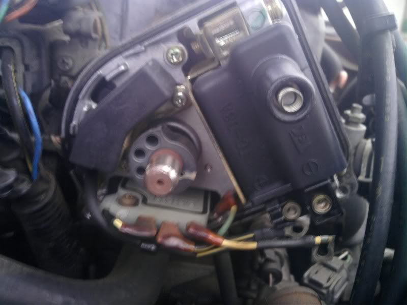
How do you check ICM and coil? Do you have to removed both of them from the distributor for testing? What should the reading be for both? You use voltage to check ICM and ohms to check resistance on coil right?
Also, what does a worn distributor rotor and terminal under the cap look like? Picture would be great.
94 Civic Ex for your reference.
Also, what does a worn distributor rotor and terminal under the cap look like? Picture would be great.
94 Civic Ex for your reference.
Last edited by PassportEX; 12-29-2009 at 06:10 PM.
 12-30-2009, 04:25 PM
#2
Platinum Member
Join Date: Jun 2006
Location: cardboard box
Posts: 1,266
Likes: 0
Received 0 Likes
on
0 Posts
Im not sure what ICM means, but I will assume that its the Igniter Unit. To check the igniter unit, first check voltage on each terminal with the ignition switch to on position. Then check the continuity between each terminal and ground.
To test coil, remove the wires from the two terminals, then check resistance between the terminals. Yes, you use ohms to check resistance.
I cant really tell you what a worn rotor looks like because I've seen the nastiest looking terminals, with no visible metal, and the car would run fine. They're cheap, just replace the cap and rotor.
12-30-2009, 08:39 PM
#3
Junior Member
Thread Starter
Join Date: Apr 2005
Location: United States of America
Posts: 216
Likes: 0
Received 0 Likes
on
0 Posts
Yes, that's right the ICM is the ignitor. I've check that and I am getting voltage. I also got it verify at the auto parts store as well.
As for the coil do you what the reading should be the primary and secondary winding on a D16z6?
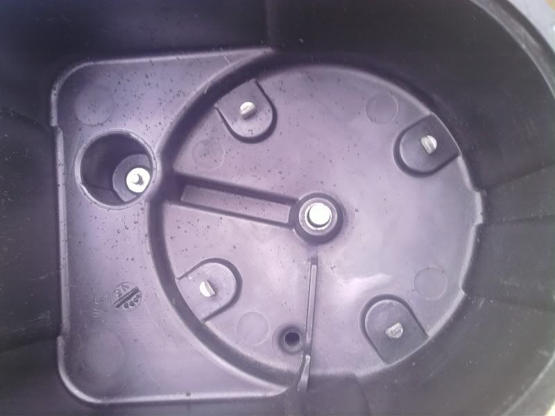
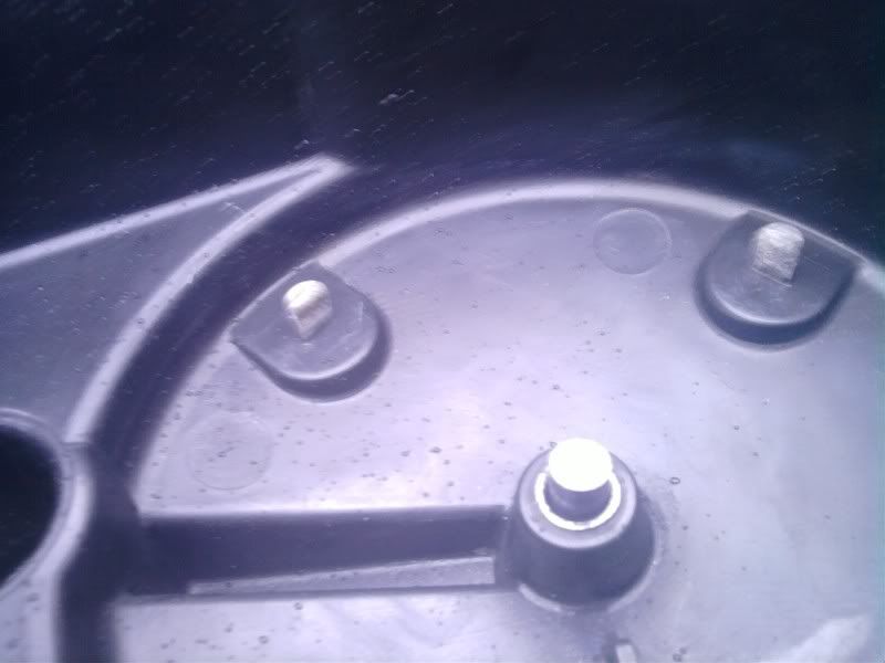
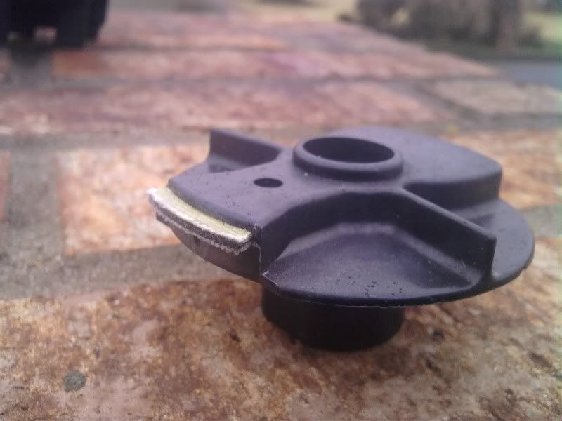
Here is a picture of my cap and rotor. Let me know what's your opinion is on it.

As for the coil do you what the reading should be the primary and secondary winding on a D16z6?
Here is a picture of my cap and rotor. Let me know what's your opinion is on it.
01-01-2010, 10:09 AM
#4
Platinum Member
Join Date: Jun 2006
Location: cardboard box
Posts: 1,266
Likes: 0
Received 0 Likes
on
0 Posts
Yeah they look fine, just that the rotor is a bit burned up. Just file down the metal part until you get a little metal showing, do the same with the terminals on the cap. Just dont use sandpaper, you need to keep the edge square.
From the Chilton, manual: The resistance btwn. terminals should be 0.6-0.8 ohms. The resistance btwn terminal A and coil tower should be 12,800-19,200ohms.
From the Chilton, manual: The resistance btwn. terminals should be 0.6-0.8 ohms. The resistance btwn terminal A and coil tower should be 12,800-19,200ohms.
01-30-2010, 09:02 AM
#5
v-card member alpha
Join Date: Oct 2006
Location: Assplosion, NE
Posts: 4,010
Likes: 0
Received 0 Likes
on
0 Posts
^ that first resistance spec. (called primary I think) (not that the Chilton is wrong) is almost certainly going to be different when you test the coil. Seems it's always higher on Civic and Integra coils (maybe others) but as long as it's below 2ohms for the primary and as long as the secondary (between A and the coil tower) is within those specs. that Line7 gave you, the coil is working.
You should clean off any contact points including rotor and then blow it out of the cap (w/ your breath, compressed air, or just a large soft brush) so it's clean inside, including the tunnel that the coil tower goes into.
You should clean off any contact points including rotor and then blow it out of the cap (w/ your breath, compressed air, or just a large soft brush) so it's clean inside, including the tunnel that the coil tower goes into.
Last edited by A-series; 01-30-2010 at 09:05 AM.